


Thermodynamic Analysis: Pairing Heat Pump Water Heaters (HPWH) with CSA B55.1 Drain Water Heat Recovery
A steady-state mass and energy balance evaluating the integration of CSA B55.1 tested Drain Water Heat Recovery (DWHR) units with residential hybrid Heat Pump Water Heaters (HPWHs) under winter design conditions. Includes reconciled heat balances, sensitivity analyses, published AHRI equipment performance metrics, and a CSI MasterFormat specification guide.
Summary of Engineering Findings (Steady-State Equal Flow)
- Volumetric Tank Draw Reduction (11.3% to 16.9%): At baseline design conditions (45.0°F mains, 105.0°F shower at 2.0 GPM, 100.0°F drain inlet, 120.0°F storage), Equal Flow DWHR preheating potable water to 68.2°F (TDX3350) or 75.3°F (TDX3615) reduces the 120.0°F tank draw rate from 1.60 GPM down to 1.42 GPM (-11.3%) or 1.33 GPM (-16.9%), respectively.
- Instantaneous Net Tank Load Cut (38.6% to 50.5%): Preheating cold supply water to 68.2°F–75.3°F at the HPWH inlet reduces the instantaneous thermal power required from the water-heating system from 60,000 BTU/hr down to 36,840 BTU/hr (-38.6%) or 29,730 BTU/hr (-50.5%).
- Reconciled Enthalpy Depletion Rate: With an active HPWH compressor delivering ~4,200 BTU/hr thermal output during the draw, a TDX3350 DWHR recovers 23,160 BTU/hr, reducing the net storage heat depletion rate from 55,800 BTU/hr down to 32,640 BTU/hr (a 41.5% slower rate of stored heat depletion).
- Sensible Tank Reheat Energy (-30.9%): Reheating the calculated 33.8 gallons of depleted storage volume from 68.2°F to 120.0°F requires 14,590 BTUs vs. 21,125 BTUs for 45.0°F unheated mains water, representing a 30.9% reduction in recharge energy (and ~31% lower compressor runtime under equivalent ambient conditions).
- Distinct Standards Framework: CSA B55.1:20 (R2025) governs laboratory performance testing (efficiency and pressure drop < 2.5 psi); CSA B55.2:20 governs materials and double-wall vented air-gap construction. Building energy code credits and rating impacts (HERS, ERI, HOT2000) depend on project-specific simulation models.
1. Design Assumptions & System Boundaries
To establish transparency for mechanical peer reviews, all thermodynamic balances in this document are calculated under the explicitly stated boundary conditions below. Performance under alternate site conditions is evaluated in the sensitivity matrix in Section 3.
Design Operating Parameters (Equal Flow Configuration):
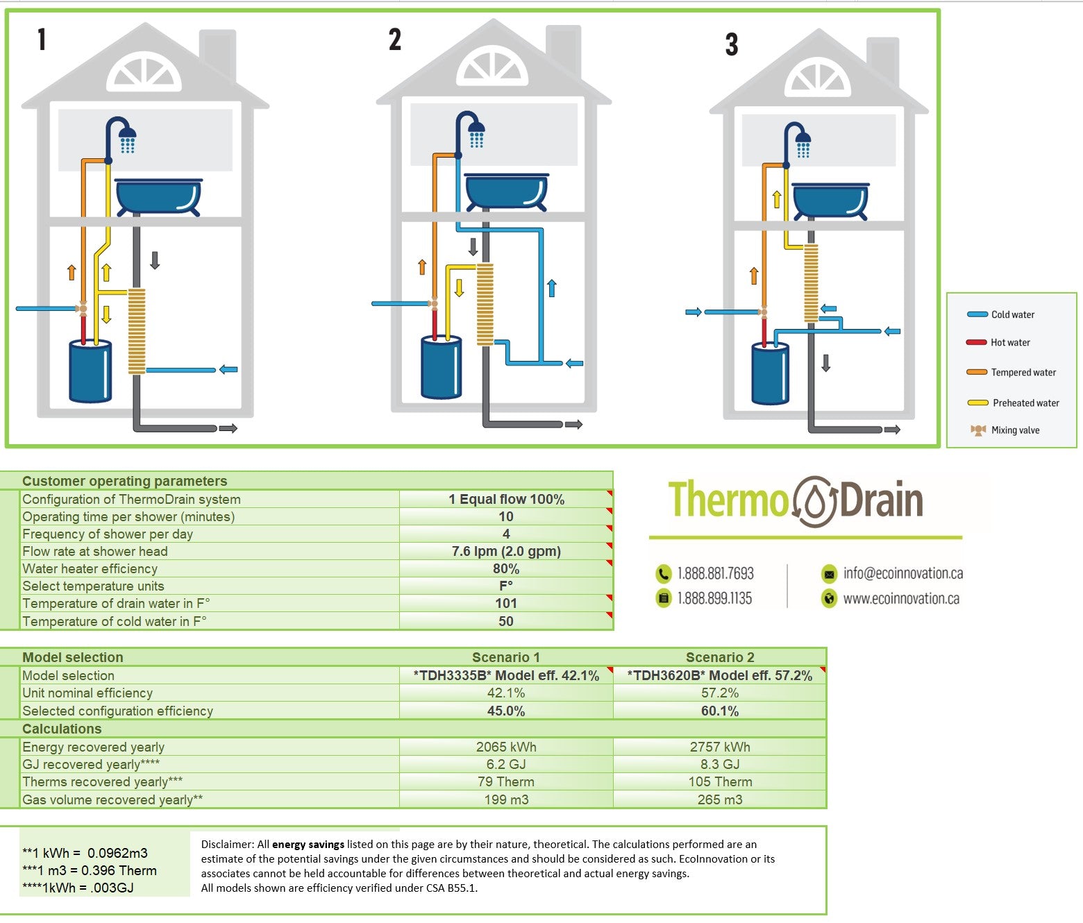
- Plumbing Architecture: Equal Flow arrangement (100% of potable cold water feeding the shower branch passes through the DWHR coil before splitting to supply both the water heater cold inlet and the shower thermostatic mixing valve).
- Total Shower Flow Rate (Qs): 2.00 GPM (7.57 L/min) steady-state. Single fixture operating concurrently; non-concurrent laundry, dishwasher, or lavatory draws.
- Mixed Showerhead Delivery Temperature (Ts): 105.0°F (40.6°C).
- Drain Inlet Temperature (Td): 100.0°F (37.8°C), establishing a 5.0°F sensible heat loss between the showerhead and the vertical stack entrance (accounting for spray cooling, receptor pan conduction, and trap arm transport).
- Incoming Winter Municipal Cold Main (Tc,in): 45.0°F (7.2°C), typical for Climate Zones 4–7 during winter design months.
- HPWH Storage Setpoint (Th): 120.0°F (48.9°C), uniform tank temperature prior to draw initiation.
-
DWHR Effectiveness (η): Evaluated at published CSA B55.1:20 rated laboratory efficiencies: 42.10% for ThermoDrain
TDX3350and 55.04% for ThermoDrainTDX3615. Rated test values are applied directly without empirical field adjustments. - Compressor Active Thermal Output: Assumed at ~4,200 BTU/hr (1.23 kW) based on published Rheem ProTerra manufacturer specifications at standard AHRI 67.5°F DB / 57.5°F WB ambient conditions. In unconditioned basements below 50°F, heat pump output decreases.
2. Reconciled Steady-State Heat & Mass Balance Equations
Under steady-state continuous flow, the mass and energy balances across the mixing valve, DWHR exchanger, and storage tank are governed by Equations 1 through 5:
(Eq. 2) 120°F Tank Draw Rate: Q_h = Q_s × (T_s − T_pre) / (T_h − T_pre)
(Eq. 3) Total Showerhead Demand: q_shower = 500 × Q_s × (T_s − T_c,in)
(Eq. 4) Heat Recovered by DWHR: q_dwhr = 500 × Q_s × (T_pre − T_c,in)
(Eq. 5) Net Thermal Tank Load: q_tank = 500 × Q_h × (T_h − T_pre) = q_shower − q_dwhr
| Thermodynamic Parameter | Baseline (No DWHR) Tc = 45.0°F |
With TDX3350 η = 42.10% (CSA B55.1) |
With TDX3615 η = 55.04% (CSA B55.1) |
|---|---|---|---|
| Preheated Potable Temp (Tpre) | 45.0°F | 68.2°F (+23.2°F lift) | 75.3°F (+30.3°F lift) |
| Tank Hot Water Flow (Qh) | 1.60 GPM | 1.42 GPM (-11.3% vol.) | 1.33 GPM (-16.9% vol.) |
| Cold Mixing Bypass Flow (Qc) | 0.40 GPM (at 45.0°F) | 0.58 GPM (at 68.2°F) | 0.67 GPM (at 75.3°F) |
| Total Showerhead Demand (qshower) | 60,000 BTU/hr (17.58 kW) | 60,000 BTU/hr (17.58 kW) | 60,000 BTU/hr (17.58 kW) |
| Heat Recovered by DWHR (qdwhr) | 0 BTU/hr | 23,160 BTU/hr (6.79 kW) | 30,270 BTU/hr (8.87 kW) |
| Net Thermal Load on Tank (qtank) | 60,000 BTU/hr | 36,840 BTU/hr (-38.6%) | 29,730 BTU/hr (-50.5%) |
| Active Compressor Output (Nominal) | 4,200 BTU/hr (1.23 kW) | 4,200 BTU/hr (1.23 kW) | 4,200 BTU/hr (1.23 kW) |
| Net Stored Enthalpy Depletion Rate (qtank − qcomp) |
55,800 BTU/hr deficit | 32,640 BTU/hr deficit (-41.5%) | 25,530 BTU/hr deficit (-54.2%) |
3. Multi-Variable Sensitivity Analysis Matrix
Because field conditions vary by geography, plumbing layout, and occupant behavior, Table 2 illustrates system response across varying cold water main temperatures (Tc,in), drain inlet temperatures (Td), and shower flow rates (Qs) using the ThermoDrain TDX3350 (η = 42.10%):
| Simulation Case | Mains (Tc,in) | Drain (Td) | Flow (Qs) | Preheat (Tpre) | Tank Draw (Qh) | Baseline Qh | Net Load Reduction |
|---|---|---|---|---|---|---|---|
| Case 1: Winter Baseline | 45.0°F | 100.0°F | 2.00 GPM | 68.2°F | 1.42 GPM | 1.60 GPM | -38.6% (-23,160 BTU/h) |
| Case 2: Mountain / Deep Winter | 40.0°F | 98.0°F | 2.00 GPM | 64.4°F | 1.46 GPM | 1.63 GPM | -38.3% (-24,420 BTU/h) |
| Case 3: Moderate Shoulder Season | 55.0°F | 100.0°F | 2.00 GPM | 74.0°F | 1.35 GPM | 1.54 GPM | -38.0% (-18,950 BTU/h) |
| Case 4: WaterSense Low-Flow | 45.0°F | 98.0°F | 1.50 GPM | 67.3°F | 1.07 GPM | 1.20 GPM | -37.3% (-16,730 BTU/h) |
| Case 5: Conservative Trap Loss | 45.0°F | 95.0°F | 2.00 GPM | 66.1°F | 1.44 GPM | 1.60 GPM | -35.1% (-21,050 BTU/h) |
4. Model-Specific HPWH Comparison: Storage Duration & Recovery Energy
A passive DWHR unit does not alter the physical storage capacity of a water heater or replace published manufacturer ratings. A standalone 80-gallon tank stores more initial thermal energy than a 50-gallon tank. However, by reducing the volumetric draw rate (Qh) and replenishing the tank with preheated water, DWHR extends calculated shower duration for a given tank size and reduces the thermal energy needed to recharge it.
Table 3 details published performance data from the AHRI Directory alongside theoretical delivery and reheat calculations for three benchmark configurations under the baseline design shower profile:
| System Parameter | 50-Gal HPWH (Standalone) Rheem PROPH50 T2 RH375-SO |
50-Gal HPWH + TDX3350 Equal Flow (68.2°F Preheat) |
80-Gal HPWH (Standalone) Rheem PROPH80 T2 RH375-SO |
|---|---|---|---|
| Nominal / Rated Storage Volume | 50 Gallons (45.0 gal actual) | 50 Gallons (45.0 gal actual) | 80 Gallons (72.0 gal actual) |
| AHRI First-Hour Rating (FHR)* *Standardized appliance rating |
67 Gallons (Hybrid Mode) | 67 Gallons (Appliance FHR) + Downstream DWHR preheat |
87 Gallons (Hybrid Mode) |
| Uniform Energy Factor (UEF) | 3.75 UEF | 3.75 UEF (Appliance rating) | 3.88 UEF |
| Estimated Usable Storage (0.75 Draw Factor) | ~33.8 Gallons at 120.0°F | ~33.8 Gallons at 120.0°F | ~54.0 Gallons at 120.0°F |
| 120°F Tank Flow Draw (Qh) | 1.60 GPM | 1.42 GPM (-11.3% vol.) | 1.60 GPM |
| Calculated Continuous Shower Run Time (Theoretical duration, Vusable / Qh) |
21.1 Minutes | 23.8 Mins (+12.8% run time) 25.4 mins with TDX3615 |
33.8 Minutes |
| Sensible Reheat Energy for Depleted Volume (33.8 gal depleted storage recharge) |
Heat from 45.0°F to 120.0°F: 21,125 BTUs (6.19 kWh) |
Heat from 68.2°F to 120.0°F: 14,590 BTUs (-30.9% BTUs) |
Heat 54.0 gal from 45.0°F to 120.0°F: 33,750 BTUs (9.89 kWh) |
Interpretation of Results: The standalone 80-gallon tank provides a longer continuous shower draw on a single continuous discharge (33.8 minutes calculated vs. 23.8–25.4 minutes) due to its larger stored physical volume. However, across spaced draws, the 50-gallon tank with TDX3350 requires 30.9% less sensible thermal energy (14,590 BTU vs. 21,125 BTU) to return its depleted volume to 120.0°F because it was refilled with 68.2°F preheated water. Assuming equivalent ambient conditions and constant compressor thermal output (~4,200 BTU/hr), this corresponds to ~31% less compressor operating time to reheat the volume.
5. Electrical Code Scope & Low-Amperage 120V HPWH Applications
Mechanical engineers and electrical designers must maintain a strict boundary between appliance branch circuit requirements and whole-building electrical service calculations:
- Branch Circuit Sizing (NEC Article 422): DWHR is a completely passive copper heat exchanger. Installing DWHR does not alter the electrical branch circuit sizing, breaker amperage, or conductor gauge specified on a water heater’s nameplate. A standard 240V hybrid HPWH with dual 4,500W electric resistance backup elements still requires a dedicated 240V / 30A branch circuit.
- Application to Dedicated 120V/15A Plug-In HPWHs: Where DWHR provides a significant design advantage is in projects utilizing dedicated 120V/15A plug-in HPWHs (such as the Rheem ProTerra 120V Shared-Circuit model or A.O. Smith Voltex 120V, drawing ~400W–500W compressor-only with zero resistance elements). Because these units lack high-wattage resistance elements, their recovery rate is limited to compressor capacity (~4,200 BTU/hr).
- Preventing Cold Climate Tank Upsizing: Manufacturers frequently recommend upsizing 120V compressor-only HPWHs to 66- or 80-gallon tanks in cold climates to prevent hot-water runout. Pairing a compact 50-gallon 120V HPWH with an Equal Flow ThermoDrain reduces instantaneous shower thermal load by 38.6% to 50.5%, buffering the slower recovery rate and allowing 50-gallon 120V units to perform reliably within existing panel capacity constraints.
6. Standards Framework (CSA B55.1 / B55.2) & Energy Modeling
Project teams must distinguish between product physical testing standards and whole-building energy simulation results:
- CSA B55.1:20 (R2025) — Performance Test Standard: Establishes the standardized laboratory test method for measuring steady-state thermal efficiency (%) and potable water-side pressure loss (psi/kPa) at 9.5 L/min (2.5 GPM). ThermoDrain units are third-party tested and listed in accordance with CSA B55.1 with pressure loss < 2.5 psi (17.2 kPa) at 2.5 GPM.
- CSA B55.2:20 — Safety & Material Standard: Specifies physical construction, material durability, and vented double-wall air-gap requirements to protect potable water against greywater cross-contamination. ThermoDrain units are certified to CSA B55.2.
- Statutory Code Recognition: Certain building codes award fixed prescriptive credits based directly on CSA B55.1 ratings. For example, under the Washington State Energy Code (WAC 51-11R-40621 Table R406.3 Option 5.1), an Equal Flow DWHR unit rated ≥ 40.0% under CSA B55.1 (such as the TDX3350 at 42.10%) is awarded 0.5 prescriptive energy credits.
- Whole-Building Performance Modeling (HERS / ERI / HOT2000): In simulation software (Ekotrope RATER, REM/Rate under ANSI/RESNET/ICC 301, and NRCan HOT2000 v11.10b), savings cannot be stated as universal constants. In a typical 2,400 sq. ft., 3-bedroom single-family reference home in Climate Zones 4–7, modeling an Equal Flow DWHR unit (42.1%–55.0% efficiency) typically yields a 15% to 30% reduction in annual water-heating energy consumption, which corresponds to an estimated 1.5 to 3.5 point whole-house HERS/ERI Index improvement. Always perform project-specific simulations.
7. Architectural Constructability & MEP Coordination
To streamline architectural detailing and field installation, project drawings should coordinate the following mechanical and structural requirements:
| Model Number | Stack Diameter | Unit Length | CSA B55.1 Eff. | Required Clear Chase Height |
|---|---|---|---|---|
| TDX3240B | 3.0" (76 mm) | 24.0" (610 mm) | 33.59% | 32" min. (fits restricted crawlspaces/basements) |
| TDX3350 | 3.0" (76 mm) | 35.0" (889 mm) | 42.10% | 44" min. (standard residential basement/chase) |
| TD442 | 4.0" (102 mm) | 42.0" (1067 mm) | 46.20% | 52" min. (commercial & multifamily 4" stacks) |
| TDX3615 | 3.0" (76 mm) | 61.5" (1562 mm) | 55.04% | 72" min. (two-story continuous vertical drops) |
- Wall Chase Integration: Unit outer diameter across copper wraps is approximately 3.375" (for 3" stack models), fitting completely inside standard 2×4 (3.5" cavity) or 2×6 plumbing walls without structural furring.
- Drain Connection: Factory-fitted ABS or PVC solvent-weld hubs connect directly into rigid DWV piping using standard solvent cement—eliminating mechanical rubber shielded couplings.
- Potable Water Supply: Factory 3/4" PEX fittings comply with ASTM F1807 (crimp) and ASTM F1960 (cold expansion). Minimum R-3 pipe insulation shall be installed on exposed preheated potable lines per IECC R403.5.3.
- Acoustic & Firestop Coordination: Where vertical drain stacks penetrate fire-resistance-rated floor-ceiling assemblies, install an intumescent firestop collar listed under ASTM E814 / CAN/ULC-S115. Maintain minimum 1/2" clearance to drywall framing to avoid acoustic bridging.
8. CSI MasterFormat 3-Part Guide Specification (Section 22 31 16)
Architects and mechanical engineers can copy and paste this specification block directly into MasterFormat Section 22 31 16 (Domestic Water Heat Exchangers) or 22 33 30 (Residential Water Heaters):
PART 1 — GENERAL
1.1 SECTION INCLUDES: Vented double-wall falling-film drain water heat recovery units for domestic potable water preheating.
1.2 QUALITY ASSURANCE: Unit shall be tested in accordance with CSA B55.1:20 (Performance Test Method) and certified to CSA B55.2:20 (Material and Safety Standard). Potable-side pressure drop shall not exceed 2.5 psi (17.2 kPa) at 2.5 GPM (9.5 L/min).
PART 2 — PRODUCTS
2.1 ACCEPTABLE MANUFACTURER: EcoInnovation Technologies Inc. (ThermoDrain Series TDX/TD).
2.2 PRODUCT SPECIFICATION: Model [TDX3350 (3" stack, 42.10% eff.) / TDX3615 (3" stack, 55.04% eff.) / TD442 (4" stack, 46.20% eff.)]. Exchanger shall feature seamless Type DWV copper drain core with exterior mechanically bonded double-wall copper potable wrap and vented atmospheric path between fluid streams.
2.3 CONNECTIONS: Drain connections shall be factory ABS or PVC direct solvent-weld hubs. Potable water connections shall be factory 3/4" PEX (ASTM F1807 / ASTM F1960).
PART 3 — EXECUTION
3.1 INSTALLATION: Install unit vertically on primary shower drain stack, not exceeding 5 degrees from plumb. Support stack above and below unit using rigid pipe clamps.
3.2 PIPING CONFIGURATION: Plumb in Equal Flow arrangement: route potable preheated outlet to feed both the cold inlet of the primary domestic water heater and the cold inlet port of the primary shower thermostatic mixing valve. Provide full-port isolation valves and drain port on potable inlet/outlet.
3.3 INSULATION: Insulate all exposed preheated potable piping with minimum R-3 closed-cell elastomeric pipe insulation complying with IECC Section R403.5.3.
Need CSA B55.1 Test Reports or Equal Flow CAD Schematics?
EcoInnovation supports mechanical engineers, architects, and energy raters with third-party CSA test certificates, BIM/Revit families, and direct volume pricing.










No comment yet, add your voice below!